ß 40m/20m Mico-Dual Bander – Part VIII

It has been a long while.  Life got in the way.  Now I’ve gotten the bug again and doing some “ham” radio stuff again.

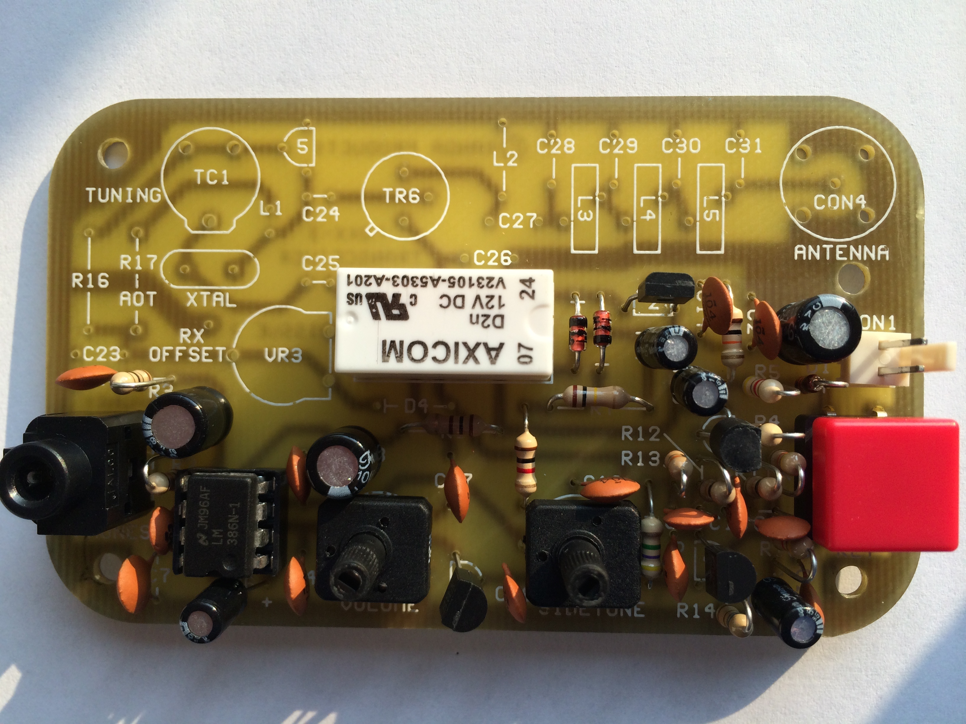
Last time I had finished building the 40 and 20m Radi0Kits.

Having spent some time away from building stuff I went back and looked over my idea of trying to cram everything into the tiny case I had.  Reality hit and I’ve decided trying to get everything into the space would be beyond my capability to keep things neat and tidy.  That and I had a kit that would be a better fit.  Now I had to find a new case, so I went to the local office supply store and found these.

IMG_3116 2

I got two sizes.  The pictures show the containers next to the built kits, a 9v battery, and the Hendrick SWR Bridge I’m going to use. The clear containers are a little smaller than the size of the original black enclosure I was going to use.

I’ve decided to use the blue enclosure.

One nice thing I discovered is that the lids of the small enclosure fit nicely into the large one.

IMG_3117 2

They are just a little too tall.  You can see the black scribe marks that I used to mark the actual height. The perspective makes them look at the wrong height.  I’m going to mount the two kits back to back and use the cut off lids as a spacer/insulator.

Using an Exacto I cut two lids to size and epoxied them back to back. Now I had a two sided drawer.  Here is a photo before trimming and bonding the top edges together.

IMG_3118 2

Next, I had to figure out how to mount the kits to the drawers. I considered screws and nuts but with two back to back there was no room.  I also wanted to be able to easily get to the boards if I needed to. I decided on hook/latch tape (Velcro®).

Here is the general idea.

IMG_3119 2

The tape doesn’t really bond to the circuit board well over the solder connections, but it has enough grip to not fall off when pressed down to the circuit board over the soldered connections.

Now I needed to make sure the boards would hold and the drawers would allow the lid to close.  I tried the drawers aligned with the narrow edge of the blue container and it was a perfect fit.  Then it hit me.  Aligned this way I had no room to route the connections from one side (one of the kits) over to the other.  I had another problem.  How to secure the drawers to the case itself.

Playing around with different positions I hit upon the following one.

IMG_3120 2

The photo shows the two boards Velcro™-ed to the drawers. In this position I can route connections to the front and back and over to the side from both kits.  Additionally, it turns out the size is just right so that when the top lid of the blue box is secured it’s a pressure-fit and is enough to hold the entire assembly tightly in place.

It’s not as neat and tidy as I had hoped but it is definitely better than the original version would have been.

Next time, I hope to have the power LED and BCI filter circuits done.  I ordered a bi-color LED whose color will indicate the band being powered.  (If I don’t blow it up first).

Posted in Uncategorized | Leave a comment

ß 40m/20m Micro Dual Bander – Step 7

A quick update.

Step 7:  I’ve built the 20m and 40m Radi0Kits over the past couple of evenings.  Here they are with a battery clip as a size comparison.  The 20m is on the left, 40m on the right.  I’ve used a Sharpie® to mark them so I know which is which.  I’ve also used machine pins as crystal sockets.

Radi0Kits

Radi0Kits 20m and 40m

I’ll test them out over the weekend.  Size-wise they will fit front-to-front in a stack into the enclosure.  If I bend the crystals outward, I can get about 3/4″ additional headroom on the overall height.

Looking at the circuit, it looks like there is some BCI compensation already.  I might forego adding a BCI filter into the enclosure. Maybe I’ll put in a small audio amp, but that would require some additional work for the battery. I’d have to figure out how to drive both one of the kits plus the audio amp off of the same supply, and I doubt a single 9v would work.  Maybe I’ll keep it simple.

The PCB boards have an usual mounting hole size. the #6 machine screws are too big and the holes are too close to the PCB board edge to drill out more, so I ordered some #4 screws, those should be small enough in diameter to fit.

Posted in Kit Building, QRP | Tagged , , | Leave a comment

A Micro Dual Band Project

I’ve been toying with the idea of getting an Elecraft K1, but the price and given that I’m not comfortable with CW is a show-stopper.  I’ve also been looking for a tiny multi band kit, but the ones out there aren’t tiny enough.

Having recently just built the Radi0Kit 140  and impressed at the little rig’s receiver and small size, I came up with an idea.  Why not combine two of these into a single rig? I did this with my original Pixie (40/80) but it wasn’t a good build quality-wise.  So here is the plan.  It’s not going to be an Elecraft K1, but it will be about 1/10th the price and be dual band, and it will be about 3x3x2″.

Step 1: Get the kits (I got a 40 and 20m kit off of eBay.  They ship from Greece, so I’m calling my little rig the ß (beta as in 2).

Kits

Radi0Kit 140 and 120 (40m, 20m)

Step 2: Get a case of minimal size with some “head room” for connectors and such.  I got a 3x3x2 enclosure from http://polycase.com.

Polycase enclosure

Polycase enclosure

Step 3: Mark the mounting holes in the case prior to building the kits (yes, I’ve done it the other way. Ugh.)

Step 4: What do I want to add? I’m going to try to incorporate the Hendrick’s Tayloe SWR Indicator and Bridge. I have one lying around I built a while back. I’ll pull it from its aluminum frame and that will give me a board that is approximately  1-3/4″ x 1″ x 3/4″. I also want to include a small BCI filter on the output which I can build on a tiny PCB or perfboard.  A power LED would be good and I’ll use a DPST center off switch to switch bands and power.  I’ll isolate the boards/bands with a few diodes.  I could include a small audio amp/speaker but that would be pushing my abilities to cram things neatly.  Likewise, a 9v battery would work, but I’ll just add a power connection so I can run off of batteries or plug it in.  So now we have to fit:

  • 2 PCB boards in a stack.
  • 1 SWR Indicator / Bridge board.
  • 1 DPST center off band/power switch.
  • 2 LEDs (power and the one that comes with the SWR I/B.
  • 1 BCI filter board
  • 1 audio jack for headphones
  • 1 key jack
  • 1 BNC antenna connector
  • 1 power connector

Step 5: Brainstorm an initial case layout (Close to scale, but not exact).  The SWR I/B and BCI boards will be mounted on-edge. The Radi0Kit boards are just a fraction of an inch too tall to fit on-edge.

Preliminary layout

Preliminary layout

Step 6: The main switching circuit. I’ve been looking into doing multi-band Rockmites, and in my stash of materials, I came across a nice build on N5ESE’s website.  He has a nice circuit diagram that switch the power, antenna, key, keyer and headphone jacks.  This is basically my plan.  I’ve “stolen” his diagram and reworked it, basically eliminating the keyer circuit that exists in the Rockmite, but not in the Radi0Kit.  I’m crediting N5ESE for this design (see his site for the original).

Modified N5ESE dual-band Rockmite circuit.

Modified N5ESE dual-band Rockmite circuit.

Now the real work begins…

Posted in Kit Building, QRP | Tagged , , , | Leave a comment

Miscellany

I’ve been busy elsewhere the past few days but I’ve been able to complete the Hendrick’s Deluxe Tenna Dipper.  It seems to work fine, but I have yet to really test it out.  Maybe on a new QRP antenna I’m planning.

Here is a photo of the completed unit.  I decided to omit the red acetate from the display. I like the look of the raw display and it will be less diffuse from smudges.

Hendrick's Tenna Dipper

Speaking of antennas, I got a 100’ strand of 28 gauge PolyStealth™.  For some reason this looks thinner than 28 gauge wire, but I know that’s just an illusion.  This stuff is very tough and I’m going to use it to make a 1/4 wave 40m end-fed.  The one I have now uses 28 gauge single strand hookup wire and although it hasn’t done so yet, I’m sure it will break internally at some point.  The PolyStealth™ will last longer.  Here is a photo.

PolyStealth™

I came across a tiny FM receiver on eBay.  The Motz is an FM tuner, external speaker and micro SD card player made out of solid peach wood.  The amplifier is an amazing 1.5 watts.  This little marvel has a 3-section telescopic whip antenna that looks like it does nothing but actually makes a huge difference in reception.  It’s main control is a 5 position “mini-joystic” that controls power, tuning and switching between FM and the micro SD card.  I’m tempted to take it apart but I’m betting I would only see a single IC chip and a few connectors.

Here is a photo.

Motz FM

Here is a photo with my old Apple iPos shuffle (a complete music system).  I need to make a tiny cable to interconnect the two.  The one I was able to find is overly long and silly looking.

Motz FM

I’ve also been practicing copying CW.  This seems to be an ongoing project of mine.  Progress seems to be very slow. Some days I can breeze through 10wpm on others I get stuck on things like F and Q and just freeze solid for the day.  Oh well, I keep hoping.

Finally, I’ve been reading a lot about regen receivers.  They seem to be the big thing on the net and Twitter.  I’m considering build one from a diagram.  This is something I’ve kept away from knowing how  un-handy I am.  Kits and step by step instructions are what I’ve worked with.  I’m not known for making things “neat”.  I’m also tempted to build the Beach 40 (VK3YE), this looks like a fun project and I haven’t built anything other than CW QRP kits.

There’s always something to work on.

Posted in Kit Building, QRP | Tagged , , | Leave a comment

Hendrick’s Deluxe Tenna Dipper Kit

I put a Hendrick’s Deluxe Tenna Dippier kit together today when I took an hour break from work.  This is a neat little kit to find the resonant frequency of an antenna or ATU.  The kit uses a TIny2313 microprocessor and  has a 4 digit display in two ranges (via a push switch).

The kit has a single SMT (a 5v regulator).

I’ve developed my own ay of point soldering SMTs. I use blue painter’s tape over half of the part to keep it from flying away and to help in positioning and soldering. This lets me have two hands free for soldering if needed and makes the part easier to find if I drop it.

The kit went together quickly, the only problem being the indicator LED is supposed to be soldered about 1/2″ off the board.  The LED needs to go through a hole in the case and I was a bit high.  If you’re building the kit I would suggest using the case to determine the height when soldering, rather than following the written directions.  Once adjusted, the board should fit nicely.

Testing the kit is basically powering the unit on with 6AA batteries and noting the range.  You then put a load resister (provided) across the antenna connector and the LED should go out.  I had no problems.

Tomorrow, I’ll work on painting the case and placing decals.

Here is a shot of the SMT on the blue tape and the board.


Hendrick's Deluxe Tenna Dipper.

Hendrick’s Deluxe Tenna Dipper.

And here is the SMT tinned and positioned, ready for soldering.


photo 2

Finally, the completed board ready for test.


photo 3

I soldered the battery connector to the front of the board (inserted into the back) so that I wouldn’t have to snake wires when it’s in the case.

I’ll post an update once it’s enclosed.


Posted in Kit Building, QRP | 1 Comment

A New SWL 40+ In The House

I’ve been on the lookout for two specific QRP kits or radios, one is a 4-band Elecraft K1.  The 2nd has been another Small Wonder Labs 40+.  I built one a while back and love the receiver.  I was lucky to find one on eBay last week and got it for a decent price!  Today it arrived.

I took it apart and made sure it look OK physically, then did a quick smoke test to make sure it powered on.  Well, I was lucky and I didn’t let any smoke out.  The rig works.  Not only that but it has the RIT option installed and that works as well. The SWL 40+ didn’t come with a note or any indication of its frequency range, so I did what I could and mapped out the extreme ranges with my FT-450’s receiver.

The new rig is tuned to the upper end of the 40m CW section while the one I built is tuned to the lower end, so I don’t have to retune either one.


Here is a photo comparing the two.  The one in the “Milk Luxe” box is the one I built.


The Milk Luxe is the one I built.  The one in the standard enclosure has the RIT option.

The Milk Luxe is the one I built. The one in the standard enclosure has the RIT option.


Here are the frequency ranges:

  • Mine:  7.0195 – 7.0400
  • New:   7.1040 – 7.1200 (I can probably move it down a bit).


Posted in Kit Building, QRP | Leave a comment

Radi0Kit 140 – A Quick Project

Well I have the FOXX-3 built, but I don’t seem to have any power output.  I spent several long hours checking and reheating all the joints to no avail.  I’m guessing the transistor driving the relay is shot but I don’t feel like pulling it right now.  I’m going to put the kit away and come back to it when I feel more motivated and can get a replacement.

So, I decided to put the Radi0kit-140 40m Pixie-like into an enclosure.  I’ve had the finished kit sitting around looking all naked and not hooked to anything.   I had bought the kit off of eBay and had put built it a while back.  The kit is put out by Yiannis SV1EEZ, of Radi0shop (Note: it’s the number 0 in Radi0.)  

The radio itself is an updated Pixie and much better quality than the available Pixie kits.  I just checked and I don’t see any of these available on eBay right now, so I’m not sure if they are still available.

In any case, I decided to put the board into the smallest enclose I could find around the house, which turned out to be an empty plastic chewing gum container.   

Here is the board in the container.  At the top is a momentary switch I’m using as the key, and the audio out jack is to the right of it.   The BNC antenna connector  is clockwise from that and a power switch with a 9v battery snap connector to the left of that.  The rig is fitting a square peg into a round hole, so to speak.

board in container.

board in container.

Here is a photo of the rig with the cover on and a 9v battery attached to indicate scale.

photo 2

It definitely works and puts out about 600mW using the battery.  This is definitely something you could toss into a backpack or a carry-on bag with a spool of wire in a similar container.

Posted in Kit Building, QRP | 2 Comments

FOXX-3 A Change Of Perspective

Today I spent a little time working on the FOXX-3 kit.  This is a really fun little kit to build. Everything is laid out well, the board is high quality and the instructions are well done.


I built the keyed and sidetone sections today.  I’ve been following the test instructions which require nothing apart from the circuit, battery,  earbuds, and a screwdriver.  I finished the keyer and powered up the board.  I pushed the switch that acts as the key expecting the relay to click over.  Nothing!  I tried again with the same results.  Maybe the relay was really quiet.  I tried again and with my ear to the relay.  Still nothing!  

I powered down, flipped the board and examined the soldering job I had done with a magnifier.  Everything looked fine.  No cold joints and no bridges.  I was about to give up for the day and go onto something else when I decided to try looking again. I was beginning to fear I had fried one of the transistors somehow. I picked up the board again, and peered at the soldering.  Aha!  One of the transistors in the keying circuit had an unsoldered lead.  The board was rotated differently when I had picked it up again.  The perspective and the angle of the lighting had kept me from seeing the unsoldered lead clearly.  A change of perspective definitely helps.

The lead was soldered, and the rig powered up again.  I pushed the key.  Nothing!  Maybe I had fried one of the transistors.  Touching the documented test point didn’t produce a buzz the way it had done yesterday. I suspected a short somewhere.  I touched one of the diodes close to the relay.  It buzzed!  Keying changed the buzz.  I took that to mean the relay was clicking over properly. 

The sidetone section went together without issues. Powering up and testing that worked the first time.  


Here are a couple of photos from today.  First the recalcitent keyer.  The red button is the key.  Also note the connections on this rig are mounted vertically.


Keyer section complete.

Keyer section complete.

The finished sidetone section.  The rig has independent volume and sidetone controls.

FOXX-3 Completed sidetone section.


Posted in Kit Building, QRP | Leave a comment

FOXX-3 40M QRP Kit

It’s been a long time. I won’t go into why I stepped away from the hobby but I have the itch and I’m back. A lot apparently has changed:

– Small Wonder Labs has shut down. It is a shame there are fewer good low cost kit options. This leaves more of the field to overpriced manufacturers. 

– Elecraft 4 band K1 is no longer sold and it appears it will not be updated or replaced. With few exceptions rig aesthetic design is going down. I always thought the K1 aesthetic design was wonderful. It looked “real”, now most rigs seem to be designed by taking a box and gluing things to it randomly. That’s just my opinion. 

– “Emergency” radio use is no longer as important it seems in the US. 
Shortwave broadcasts are dying. 

Wow! The good news is there are updated Rockmites from QRPme, and a ton of Chinese clones of questionable quality. I’m not sure the last is good news. 

I want a K1 4-bander. Oh well. 

So I’m getting back in to the hobby by starting a new kit. I pulled an envelope off my stack and it turned out to be a Kanga FOXX-3 I forgot I had even bought. This is a 40m kit.

The kit looks like it is high quality and the packaging is organized by stages which is unusual for kits like this. The documentation is well done with explanations of the stages and test procedures after each stage is built. 

Here are some photos. First the kit:

QRP Kit

QRP Kit

The board:

FOXX-3 Board

The amplifier stage done and tested out correctly:

FOXX-3 Amplifier Test

I’m glad to be back!

Sent from Auteureist™

Posted in Uncategorized | Leave a comment

MFJ Iambic Paddle Kit

This is a quick post about a tiny kit I just got and put together.

I’ve been working in learning CW and as part of that I have read that you should start with an iambic paddle rather than a straight key. Well, I have a straight key and built a tiny one as well, but had no iambic paddles.

If you have priced keys and or iambic paddles you know they can run hundreds of dollars and although they look marvelous, they are useless unless you know how to use them. After several hours of scouring the web I came across two cheap iambic keys.

The first is the topic of this post, the MFJ iambic paddle kit, MFJ-561K which is a tiny kit. (You can also order it rebuilt). The first photo is the kit.

This is mostly a mechanical kit with a little soldering. The instructions are clear and the kit is easy to build with one exception. The first step is to insert the shoulder washers into the paddle arms, but the pre-drilled holes are too small for them. A few moments with a Dremel solved the problem and the kit went together in less than fifteen minutes.

Here is the key without the cable or feet.

I haven’t played with it yet. I’m considering whether to mount it on something. The key as is pretty much metal and has no real base, just a machined metal plate. It would fit perfectly on an Altoids tin. Maybe might next Rockmite.

Sent from my iPad

Posted in Uncategorized | Leave a comment